Difference between revisions of "Northfield-MFJ-998RT"
| Line 3: | Line 3: | ||
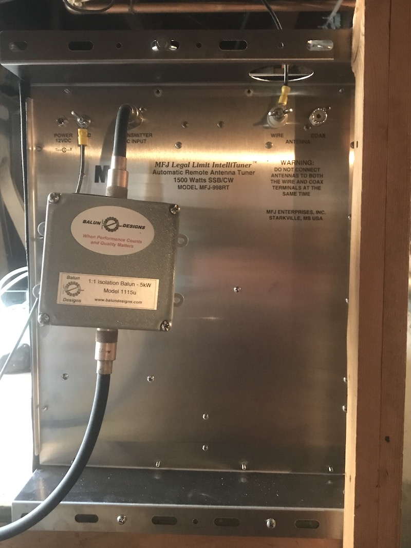
The bottom of the unit which faces toward the operating position. The ground connection is on the upper left and the antenna wire feeds through a hole on the top edge of mounting frame to its high voltage connection point on the upper right. The square box in the feed line is a Balun Designs 1:1 Isolation Balun (Model 1115u) to keep RF off the coax. The tuner is powered directly through the DC power jack mounted on the tuner itself. If mounted outdoors the unit would use the feed line and the “Bias T” unit. The tuner is held in place by a single screw into the self’s wooden vertical member seen on the black “MFJ” logo side and the bottom edge of the tuner is resting on the shelf itself so that screw is not supporting any of the tuner’s fairly substantial weight. Two small screws are also installed along the bottom edge to hold it securely in place. | The bottom of the unit which faces toward the operating position. The ground connection is on the upper left and the antenna wire feeds through a hole on the top edge of mounting frame to its high voltage connection point on the upper right. The square box in the feed line is a Balun Designs 1:1 Isolation Balun (Model 1115u) to keep RF off the coax. The tuner is powered directly through the DC power jack mounted on the tuner itself. If mounted outdoors the unit would use the feed line and the “Bias T” unit. The tuner is held in place by a single screw into the self’s wooden vertical member seen on the black “MFJ” logo side and the bottom edge of the tuner is resting on the shelf itself so that screw is not supporting any of the tuner’s fairly substantial weight. Two small screws are also installed along the bottom edge to hold it securely in place. | ||
| − | |||
[[File:MFJ998rtIMG 1025.jpeg]] | [[File:MFJ998rtIMG 1025.jpeg]] | ||
Revision as of 16:15, 8 March 2020
Contents
Installation
The bottom of the unit which faces toward the operating position. The ground connection is on the upper left and the antenna wire feeds through a hole on the top edge of mounting frame to its high voltage connection point on the upper right. The square box in the feed line is a Balun Designs 1:1 Isolation Balun (Model 1115u) to keep RF off the coax. The tuner is powered directly through the DC power jack mounted on the tuner itself. If mounted outdoors the unit would use the feed line and the “Bias T” unit. The tuner is held in place by a single screw into the self’s wooden vertical member seen on the black “MFJ” logo side and the bottom edge of the tuner is resting on the shelf itself so that screw is not supporting any of the tuner’s fairly substantial weight. Two small screws are also installed along the bottom edge to hold it securely in place.
Operating Instructions
The MFJ-998RT tuner is connected to Ant. 1 position connected to the inverted-L antenna. The tuner appears to be pretty choosy about how much “Tune” power should be applied. The TX settings has been set to use only 10 watts on the “Tune Pwr” slider adjustment. This is activated by clicking on the Tune button on the radio. Please ensure the Flex’s ATU is off and in “Bypass” mode. It can take a while for the tuner to work through its tune routine for each band, as much as up to 30 seconds. The tuner will remember its settings when you go back to a previously used frequency. The tuner has a lot of internal parameter settings and they haven’t been adjusted. Everything is still at factory default. One of the internal settings is the minimum SWR you want it to try to find. From what has been observed so far, it appears to be set to around 2:1 or less. So for now, be patient with how long it takes to find a match and don’t worry if the final match is around 2:1 +/- a little. Often it will be under 2:1 though.
60 Meter Considerations
With the new auto antenna tuner installed I have been playing around on the 60 meter band. Always use USB on 60 phone, not LSB and the maximum bandwidth allowed per channel is 2.8 KHz. There are five defined channels on 60 for us to use. There are “center frequencies” for CW, RTTY and the digital modes and there are “offset frequencies” for USB. All the activity I have heard there so far has been USB. Here are the offset frequencies for USB you can directly enter on the the Flex for phone QSOs:
5.3305 5.3465 5.3570 5.3715 5.4035
Observations from KK9H
So far I have tried it on 160, 80, 60 and 40. By the way, the inverted-L is a full-wave antenna on 40 and it has truly been “Da Bomb” for me when chasing DX due to its gain. Heaven only knows what the radiation pattern looks like, but it frequently beats my vertical by a noticeable mount. Pretty neat that we can now operate on 60 but be sure to read the exact frequencies we can use there because the the Flex programming is very precise as to where the rig will actually allow you to transmit on that band. Everything is USB on phone, but you have to adjust for the carrier frequency. You can also use CW and digital modes now too.
